Structure and Operation of USB(do read USB protocols and architecture
COMPUTER ORGANIZATIONExplanation
USB Universal Serial Bus (USB) is an industry standard developed through a collaborative effort of several computer and communication companies, including Compaq, Hewlett-Packard, Intel, Lucent, Microsoft, Nortel Networks, and Philips.
Speed -
Low-speed(1.5 Mb/s)
Full-speed(12 Mb/s)
High-speed(480 Mb/s)
Port Limitation
Device Characteristics
Plug-and-play USB TREE STRUCTURE
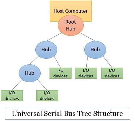
To accommodate a large number of devices that can be added or removed at any time, the USB has the tree structure as shown in the figure.
Each node of the tree has a device called a hub, which acts as an intermediate control point between the host and the I/O devices. At the root of the tree, a root hub connects the entire tree to the host computer. The leaves of the tree are the I/O devices being served (for example, keyboard, Internet connection, speaker, or digital TV)
In normal operation, a hub copies a message that it receives from its upstream connection to all its downstream ports. As a result, a message sent by the host computer is broadcast to all I/O devices, but only the addressed device will respond to that message. However, a message from an I/O device is sent only upstream towards the root of the tree and is not seen by other devices. Hence, the USB enables the host to communicate with the I/O devices, but it does not enable these devices to communicate with each other.
When a USB is connected to a host computer, its root hub is attached to the processor bus, where it appears as a single device. The host software communicates with individualdevices attached to the USB by sending packets of information, which the root hub forwards to the appropriate device in the USB tree.
Each device on the USB, whether it is a hub or an I/O device, is assigned a 7-bit address. This address is local to the USB tree and is not related in any way to the addresses used on the processor bus.
A hub may have any number of devices or other hubs connected to it, and addresses are assigned arbitrarily. When a device is first connected to a hub, or when it is powered on, it has the address 0. The hardware of the hub to which this device is connected is capable of detecting that the device has been connected, and it records this fact as part of its own status information. Periodically, the host polls each hub to collect status information and learn about new devices that may have been added or disconnected.
When the host is informed that a new device has been connected, it uses a sequence of commands to send a reset signal on the corresponding hub port, read information from the device about its capabilities, send configuration information to the device, and assign the device a unique USB address. Once this sequence is completed the device begins normal operation and responds only to the new address. USB protocols
All information transferred over the USB is organized in packets, where a packet consists of one or more bytes of information. There are many types of packets that perform a variety of control functions.
The information transferred on the USB can be divided into two broad categories: control and data.
Control packets perform such tasks as addressing a device to initiate data transfer, acknowledging that data have been received correctly, or indicating an error. Data packets carry information that is delivered to a device. A packet consists of one or more fields containing different kinds of information. The first field of any packet is called the packet identifier, PID, which identifies the type of that packet. They are transmitted twice. The first time they are sent with their true values, and the second time with each bit complemented
The four PID bits identify one of 16 different packet types. Some control packets, such as ACK (Acknowledge), consist only of the PID byte.
ELECTRICAL CHARACTERISTICS
The cables used for USB connections consist of four wires.
Two are used to carry power, +5V and Ground.
Thus, a hub or an I/O device may be powered directly from the bus, or it may have its own external power connection.
The other two wires are used to carry data.
Different signaling schemes are used for different speeds of transmission.
At low speed, 1s and 0s are transmitted by sending a high voltage state (5V) on one or the other o the two signal wires. For high-speed links, differential transmission is used.